Post by gm on Nov 6, 2017 16:45:19 GMT -8
I have questions regarding the wiring of my off grid system.
Renogy 4X100 Watt Mono panels in parallel for 400 Watts total.
Renogy Rover 40 Amp, RVR2040, MPPT Charge Controller.
VertaMax PURE SINE WAVE 3000 Watt (6000W Surge) 12V Power Inverter DC to AC Power (1/0 Cables + Remote Control Switch + ANL Fuse) – Overkill on the watts but I will occasionally use a LaserJet Printer for short periods of time (minutes).
The above are being installed on a Cargo Trailer to be used as an office/sleeping quarters.
S. The wire size chart for the Rover states I should use 10AWG. But from what little I remember from an electronics class years ago I can oversize this to the acceptable maximum wire size of 8AWG as a small margin of safety. Is this correct?
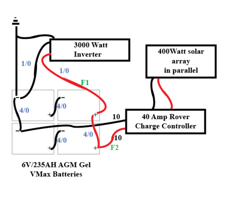
B. I read somewhere that the POS and NEG cables going to the inverter should come off different batteries than the POS and NEG leads for the controller. Supposedly this is to balance the current draw across the battery banks somehow. I would also think this makes for a smaller chance of bad connection with one lug corroding on another. Is this true and is my schematic correct for the situation?
C. The inverter came with 1/0 cables and a 50 amp fuse. Shouldn’t the cables to the inverter be 4/0 to cover the 235 A/H rating?
D. A related question to the above is the voltage drop. See: www.affordable-solar.com/solar-tools/wire-sizing-charts/ 2% voltage drop chart. This chart tells me that 4/0 has a 11 volt loss while #2 has only a 3.6 volt loss at 200 Amps. Can someone tell me why there is a greater loss with a larger conductor? That defies logic for me.
E. Fuse F2 should be rated at 40Amps, correct. The upper limit of the controller.
Thanks for the help. I may have follow up questions.
GM


 consider higher voltage panels to begin with.